|
SURFACE STRUCTURE.
A surface finishing can be described as “friendly
to the yarn” when:
- the surface does not damage the yarn
- the coefficient of friction is reproducible;
- spin finishes are not removed
These demands are satisfied by a surface with a homogeneous conformation,
consisting of rounded lines without sharp edges.
The surface of the thread guide is determined by:
- the material;
- the manufacturing process;
- the surface treatment;
a) FRICTION COEFFICIENT.
The friction coefficient is calculated by measuring the
two yarn tensions before and after the thread guide.
The equipment used to measure the friction coefficient is very simple
and is shown in the figure below. The yarn runs with constant speed. Its
input tension is determined by a tension device; the yarn runs over the
thread guide and its wrap angle is measured. Two tension meters measure
the tensions T1 and T2. The friction coefficient is calculated by Eytelwein’s
law:

Where:
T2 Input tension (T2 = 0,1 Denier + (Denier
/ Filaments))
T1 Output tension
α Wrap angle
f Friction coefficient
b) ROUGHNESS AND FINISH.
Surface roughness is a very important characteristic to
ensure smooth travel of the
thread. Therefore special attention must be paid when selecting the ideal
roughness value.
The following tables summarise the standard roughness values offered by
Bettini:
|
COATING
|
CHARACTERISTICS |
ROUGHNESS Ra |
THICKNESS |
Double layer satin finish chromium
CRBS |
Deposit comprising a softer layer
of chromium but more resistant to corrosion and a conventional layer
of chromium.
Final appearance of coating: opaque. |
> 0.6 µm |
Minimum 15 µm
(10µm + 5µm ) |
|
Double layer polished chromium
CRBL
|
Deposit comprising a softer layer
of chromium but more resistant to corrosion and a conventional layer
of chromium.
Final appearance of coating: slightly opaque |
from 0.2 to 0.4 µm |
Minimum 15 µm
(10µm + 5µm ) |
Polished chromium
CRL |
Polished finish |
Up to 0.4 µm |
Minimum 5 µm |
|
Semi-polished chromium
CRLS
|
Opaque semi-polished finish |
< 0,6 µm |
Minimum 5 µm |
Satin finish chromium
CRS
|
Opaque finish |
> 0,6 µm |
Minimum 5 µm |
|
Polished nickel
|
Polished finish |
Up to 0.4 µm |
Minimum 3 µm |
| Satin finish nickel |
Opaque finish |
> 0,6 µm |
Minimum 3 µm |
|
|
PLASMA COATING WITH
CERAMIC OXIDES |
| Coating codes |
A100 |
AT97 |
AT87 |
AT60 |
T100 |
C100 |
|
Composition
|
100%
AL2O3
|
97% AL2O3
3% TiO2 |
87% AL2O3
13% TiO2 |
60% AL2O3
40% TiO2 |
100%
TiO2 |
100%
Cr2O3 |
| Electric behaviour |
Insulating |
Insulating |
Conductor |
Conductor |
Conductor |
Conductor |
Average roughness
Ra micron |
SATIN FINISH
Ra from 4 to 8 |
POLISHED SURF.
Ra from 1 to 2 |
GROUND SURF.
Ra from 0,6 to 1 |
LAPPED GROUND LAPPED
Ra from 0,3 to 0,6 |
CAUTION: the above data are purely guideline obtained on
samples.

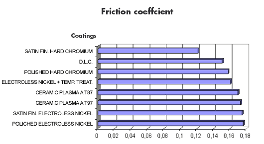
The above graph shows the friction coefficient values
related to coatings applied by Bettini.
The numerical data were obtained on samples according to international
specifications. The specified values must not be arbitrarily transferred
to all components or parts with different forms or surface finishes.
Bettini technicians are available to recommend the ideal surface finish,
to optimise roughness and the friction coefficient.
|


